Solved Examples of Comlicated Circuits
Illustration:
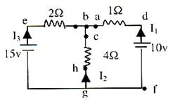
Let us analyse a simple circuit shown in the figure alongside. Assume current values (I1, I2 & I3) at random directions.
Alt txt: simple circuit
Solutions
Þ All through the branch gfdab current in I1
All through the branch geb current is I3
All through the branch ghcb current is I2
Applying KCL at b Þ I1 + I2 + I3 = 0 …… (i)
(Note: We will get the same eqn. at node g)
The voltage drops across the circuit elements in loop fdbegf,
Vd – Vf = 10V (constant voltage source)
Vd – Va = 1 × I1 (drop in the direction of current flow)
Ve – Vb = 2 × I3 (drop in the direction of current flow)
Vg – Ve = 15V (constant voltage source)
Moving anti clockwise we write,
KVL: (Vf – Vd)+(Vd – Va)+(Va – Vb)+(Vb – Ve)+(Ve – Vg)+(Vg – Vf) = 0
Þ (–10) + (I1) + (0) + (–2I3) + (–15) + 0 = 0
Þ I1 – 2I3 = 25 …… (ii)
Consider loop bchgeb. The voltage drop across the elements is,
Vh – Vc = 4I2
Ve – Vb = 2I3
Vg – Ve = 15
KVL: (Vb – Vc) + (Vc – Vh) + (Vh – Vg) + (Vg – Ve) + (Ve – Vb) = 0
Þ (0) + (–4I2) + (0) + (15) + 2I3 = 0
Þ 2I3 – 4I2 = –15 …… (iii)
Now solve (i), (ii), & (iv) simultaneously, you shall arrive at,
I1 = 120/14, I2 = 5 – 5/14, I3 = –115/14
Illustration:
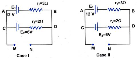
What is the potential difference between the points M and N for the circuits shown in the figures, for case l and case ll?
Alt txt : Potential-difference-between-points
Solution:
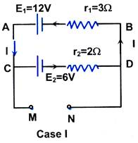
Case l:
l = E1 – E2 / r2 + r1 = 12 – 6 / 3 + 2 = 1.2 A
Alt txt: circuit-1
For cell E1: vA – E1 + lr1 = vB
i.e. vA – vB = E1 – lr1
= 12 – 1.2 × 3 = 8.4 V
For cell E2, vC – E2 – lr2 = vD
i.e. vC – vD = 6 + 1.2 × 2 = 8.4 V
Hence, vC – vD = vA – vB = vM – vN = 8.4 V
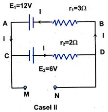
Case ll:
l = E1 + E2 / r1 + r2
= 12 + 6 / 3 + 2 = 3.6 A
Alt txt: Circuit-2
For cell E1:
vA – E1 + lr1 = vB,
i.e. vA – vB = E1 – lr1 = 12 – 3.6 × 3 = 1.2 V
For cell E2:
vC + E2 – lr2 = vD
i.e. vC – vD = –E2 + lr2 = – 6 + 3.6 × 2 = 1.2 V
Hence, vA – vB = vC – vD = vM – vN = 1.2 V
Illustration:
In the adjacent circuit, find the effective resistance between the points A and B.
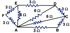
Alt txt: effective resistance between two points
Solution:
Resistors AF and FE are in series with each other. Therefore, network AEF reduces to a parallel combination of two resistors of 6 W each.
Req = 6 × 6 / 6 + 6 = 3 W.
Similarly, the resistance between A and D is given by 6 × 6 / 6 + 6 = 3 W.
Now, resistor AC is in parallel with the series combination of AD and DC. Therefore, resistance between A and C is 6 × 6 / 6 + 6 = 3 W. Now, the combination of (AC + CB) is in parallel to AB. Therefore, since AC and CB are in series, their combined resistance = 3 + 3 = 6 W. Resistance between A and B is given by, 1 / R = 1/6 + 1/3 = 3/6 or RAB = 2W.
To read more, Buy study materials of Current Electricity comprising study notes, revision notes, video lectures, previous year solved questions etc. Also browse for more study materials on Physics here.
View courses by askIITians


Design classes One-on-One in your own way with Top IITians/Medical Professionals
Click Here Know More

Complete Self Study Package designed by Industry Leading Experts
Click Here Know More

Live 1-1 coding classes to unleash the Creator in your Child
Click Here Know More

a Complete All-in-One Study package Fully Loaded inside a Tablet!
Click Here Know MoreAsk a Doubt
Get your questions answered by the expert for free