Electric Flux
Table of contents |
Introduction to Electric Flux
Electric field lines help in describing basic nature of the electric field in two-dimensional pictorial forms. What if we want to present electric field in a three-dimensional form? This can be done with the help of electric flux. Let’s understand what the term flux actually means, with an example.
Electric Flux
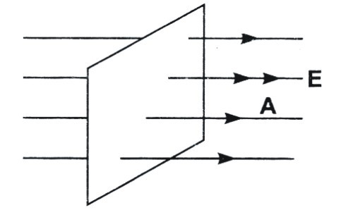
Image 1: Electric flux passing through a plane surface
Electric Flux is defined as a number of electric field lines, passing per unit area. It is another physical quantity to measure the strength of electric field and frame the basics of electrostatics. It is also defined as the product of electric field and surface area projected in a direction perpendicular to the electric field. Let’s understand what the term flux actually means, with an example.
Example:
Suppose there a liquid flowing with velocity ‘v’, through tiny surface dS, in a normal direction with respect to the surface. The rate of flow of water will be volume passing through the area per unit time that is v dS.
Volume = Area × Length
Differentiating the above relation with respect to time, we get
d Volume/ dt = dS × d length/ dt
Flow of liquid = dS × v
where dS is a surface area perpendicular to the velocity v of water, and v is the velocity of liquid (rate of change of length per unit time)
This flow of liquid, that is the quantity v dS, is called flux. If there is some angle θ between the velocity of liquid and surface area dS and flux of liquid, can be evaluated from the relation:
Flow of liquid = v dS cos θ
If we replace, an electric field with flowing water, we define it as electric flux.
Note: Flowing water and electric field are different terms, it is not necessary that something should flow in order to generate a flux.
Since the strength of electric field is directly proportional to a number of lines passing per unit area, electric flux also signifies for determining the strength of electric field. The S.I unit of electric flux is Newton meters squared per coulomb (N m2 C−1). Electric field is denoted by the symbol Φ (phi) and is represented as
Φ = E Δ S
Image 2: Electric flux varies with different orientation in electric field and area vector
Consider an area with electric field E, in it. If we place, a planar object of surface area Δ S, then a number of electric field lines passing per unit area, will be proportional to E Δ S. What if we accordingly tilt the planar object with angle θ? Then electric flux with vary and depend on the relation:
Φ = E Δ S cos θ
Observations in Electric Flux
Image 3: Electric flux in different cases
Electric Flux is a variable quantity as it depends on the direction of electric field and orientation of the planar object. Suppose you’re asked to pass out water through a ring, on which position do you expect the maximum flow of water? This will be when the area of the ring would be perpendicular to the flow of water. The same thing holds for electric flux as well. Some observations related to electric flux are as follows:
-
Electric flux becomes zero, when electric field is parallel to the surface area ΔS, as the angle becomes 90° and value of cos 90° is zero
-
The direction of ΔS is determined by area vector, as it has both magnitude and direction. Area vector’s direction is always normal and out of the plane surface
-
Electric flux becomes negative when electric field and area vector is antiparallel
-
The direction of area vector is always out of the surface
-
In case of curved surface, we evaluate ΔS by dividing a large surface area into small segments and integrate with proper limits
Applications of Electric Flux
Electric Flux forms the basic foundation of electrostatics and has many applications like:
-
Electric Flux helps in calculation of electric field
-
Electric Flux simplifies evaluation of electric field in complex figures
-
Gauss Theorem, one of the most useful theorems of electrostatics, is based mainly on electrostatics
Image 4: Direction of normal vector
Example of Electric Flux
A cube of side 2cm is placed in a region of electric field 120 N/ C. Calculate the electric flux through the
a. Top face
b. Bottom face
c. Right face
d. Left face
e. Net flux
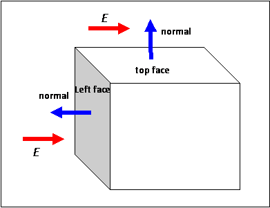
The electric field perpendicular to the left face area vector of the cube. Refer the diagram below.
Solution:
We know that electric flux is defined as
Φ = E S cos θ
where E is an electric field, and S is surface area and cos θ is the angle between area vector and electric field.
Image 5: Diagram of cube, depicting electric field and area vector on different faces
a. Top face
As electric field and area vector are perpendicular to each other, the electric flux through top face is zero (cos 90°= 0).
b. Bottom face
Through the bottom face, again the angle between area vector and an electric field is 90°, so electric flux passing through the bottom face is 0.
c. Right face
The area vector (normal) and electric field are in the same direction, so the electric field between them is 0°.
Evaluating electric flux we get
Φ = E S cos θ
Φ = 120 × (0.02)2 cos 0
Φ = 120 × 0.02 × 0.02 × 1
Φ = 0.048 N m2 C−1
d. Left face
The area vector (normal) and electric field are antiparallel in direction that is, the angle between electric field and area vector is 180°.
Evaluating electric flux we get
Φ = E S cos θ
Φ = 120 × (0.02)2 cos 180
Φ = 120 × 0.02 × 0.02 × -1
Φ = - 0.048 N m2 C−1
e. Net flux
As electric flux is a scalar quantity, we can add it algebraically to calculate the net flux.
Net electric flux = Sum of electric flux through left face, right face, top face and bottom face
= 0 + 0 + 0.048 -0.048
= 0
So the net electric flux is 0.
Watch this Video for more reference
More Readings
View courses by askIITians


Design classes One-on-One in your own way with Top IITians/Medical Professionals
Click Here Know More

Complete Self Study Package designed by Industry Leading Experts
Click Here Know More

Live 1-1 coding classes to unleash the Creator in your Child
Click Here Know More


