Introduction of Ray Optics and Optical Instruments
Table of Content |
|
|
Basic Cconcepts
Basic Concept about Ray Optics:
Electromagnetic Field
When a current flow through an object, it creates a physical field across it which is known as Electromagnetic Field. If the charges are stationary, then an electric field is created and if the charges are moving than a magnetic field is created. This electromagnetic field is mainly a combination of the electric and magnetic field which travels perpendicular to each other and spreads out infinitely throughout the space.
Electromagnetic Radiation
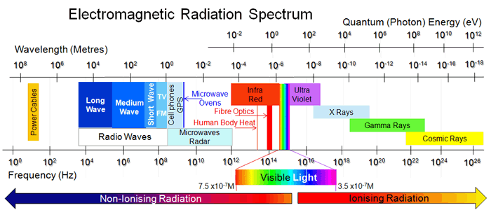
The Electromagnetic Field that propagates through space carries a radiant energy. This energy can be divided into 7 radiation namely radio Waves, Micro Waves, Infrared, Visible Lights, Ultraviolet, X-Ray and Gamma Rays based on their wavelength.
Light
The energy that is radiated within the wavelength of 400nm to 700nm and is a part of the visible light spectrum is visible to human eyes. It is due to the help of this light that human retina can perceive things around them. The naturally highest attainable speed in this world is that of light and it is equal to 3 X 10⁸ ms-1.
Ray of Light
A Ray is defined as the path that a light traverse when it is travelling from one point to another.
Beam of Light
A bunch of ray of lights is known as Beam of Lights.
Optics
Optics is basically a branch of physics that deals with the study of the interactions of lights with matter and their behaviour.
Reflection of Light
When a light travelling in air is incident on a reflecting surface material it gets reflected. The angle that the incident light makes with the normal of the surface is known as Angle of Incidence and the angle that the reflected light makes with the normal is known as Angle of Reflection.
Laws of Reflection:
-
The angle between the incident ray and normal that is, angle of incidence is always equal to the angle between normal and reflected ray that is, angle of reflection
-
The ray which is incident on the surface, the normal and the ray which is reflected back lies on the same plane.
Refraction of Light
When a ray of light after travelling through air enters a different medium, it gets diffracted from the normal or bends towards the normal depending on the medium it is entering. When a ray of light travels from lighter medium to denser medium then the light bends towards the normal. Likewise, when a ray of light travels from denser medium to lighter medium, it deviates away from the normal.
Snell’s Law or Laws of Refraction
-
The incident ray, the refracted ray and the normal lie on the same plane of incidence.
-
The ratio of the sine of angle of incidence to the angle of refraction is constant.

Where, n2/n1 is called the Refractive Index.
Total Internal Reflection
When a ray of light travels from a denser medium to a rarer medium, then a portion of it gets reflected back to the medium that it travelled and some portion enters the second medium and gets refracted. After some point, the incident ray gets totally reflected and does not suffer any further refraction. This reflection is known as Total Internal Reflection.
As we know that when a ray of light travels from a denser medium to rarer medium then it bends away from the normal.
Consider the example given below. A ray of light AO1 while travelling from denser (water) to rarer medium (air), has some of its portion reflected back to the same medium (O1C) forming an angle with the normal known as Angle of Incidence (i) while some of it portion gets refracted to the rarer medium creating a deviated angle with the normal which is known as Angle of Refraction(r).
As seen from the diagram, there is an increase in the angle of refraction as the angle of incidence increases. A point comes when the angle of refraction is 90° (AO3) and the incident ray (AO4) gets totally reflected, after which there in no refraction possible even if the angle of incidence is increased further. This angle at which, the angle of refraction is perpendicular to normal that is, 90°, and there is no further refraction is known as Critical Angle and the Reflection is known as Total Internal Reflection.
Applications of Total Internal Reflection:
-
Mirage: Mirage is basically an optical illusion wherein the observer sees an inverted image of distant tall objects. During summer, the air near the ground is hotter compared to air at higher levels. The refractive index of hotter air is less than the cool air. So when light from a tall object travels from cool air (denser medium) to hot air (rarer medium), total internal reflection occurs, as a result of which the observer sees an inverted image of the object.
-
Diamond: Diamonds are popular for their gloomy appearance. Naturally occurring diamonds does not have such property of shine. It is the technique of the diamond cutter who cuts and shapes diamond in such a way that, when light enters the diamond, it goes multiple total internal reflections. The refractive index of diamond is almost equal to 24.4° which is very small.
-
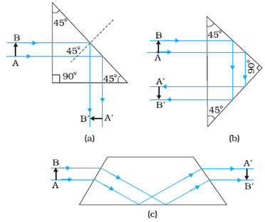
Prisms: A prism is designed at such an angle that when light enters the prism, it undergoes total internal reflection at 90° or by 180°, which in returns produces an inverted image of the object without changing their size.
-
Optical Fibre: Optical Fibres are made of glass/ quartz material. An optical fibre consists of two parts: a) core and b) cladding. The refractive index of the cladding is less than that of core. When data in the form of light is transmitted in optical fibre from one end than, it goes repeated total internal reflection and comes out from the other end without suffering any loss during the transmission. Optical fibres are most widely used for signal and video transmission. The most important advantage of optical fibre is that, even if the fibre is tweaked somewhere, there is no loss in data while transmission.
Spherical Mirrors and their types
Consider a glass with a hollow sphere and a reflecting surface. This reflecting hollow surface of the glass forms the spherical mirrors. Spherical mirrors are of two types:
a) Concave Mirror and b) Convex Mirror: Consider the diagram given below. The inward curved reflecting surface of the spherical mirror as seen in the figure below is known as Concave Mirror and the outward curved reflecting surface of the same spherical mirror is known a Convex Mirror.
Centre of curvature of Spherical Mirrors
The centre of the hollow sphere which is a part of the spherical mirror is known as the centre of curvature. This is denoted by the letter ‘C’.
Pole of Spherical Mirrors
Pole of Spherical Mirror is the centre of the spherical mirror. It is denoted by the letter ‘P’. Kindly, note the difference between the centre of curvature and pole. Former is the centre of hollow sphere, whereas the latter is the centre of spherical mirror. For better understanding, consider the diagram given below:
Radius of curvature of Spherical Mirrors
The radius between the centre of curvature ‘C’ and the Pole of the spherical mirror ‘P’ is known as Radius of curvature.
Principal axis of a Spherical Mirror
It is a straight line joining the pole of the spherical mirror and the centre of the spherical mirror. In the above diagram XY is the principal axis.
Focal Length of a Mirror( f)
The focal length of a mirror is defined as the distance which is half of Radius of curvature, that is,

where f is the focal length and R is the radius of curvature.
Q. If the radius of curvature of a spherical mirror is 50 cm, then find it focal length?
= 50/2
= 25 cm
Sign Conventions
The Cartesian Sign Conventions that are considered while deriving the formulae for reflection and refraction by spherical mirror and lens respectively is given below:
-
If the distance is measured in the direction same as that of the incident light, then the direction is taken to be positive while the distance measured in opposite direction is taken to be negative.
-
The heights measured in upward direction normal to principal axis is considered positive while the height measured in downward direction normal to principal axis is considered negative.
Mirror Equation
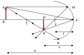
Let us consider the diagram below to understand the process of image formation:
Let AB be an object and the distance of AB from the pole be ‘u’. ‘u’ is also known as object distance. An infinite number of rays travel from point A. But for time being let us consider only three rays that is, ray AM, AP and AN. The ray AN gets reflected back in the same direction that it travelled. As seen from the diagram the reflected rays of all the three rays intersect at a point where an inverted image of the object is formed. This is the real view of the original object. The distance at which the inverted image formed away from the pole is denoted by ‘v’. This distance is also known as Image Distance. Then the mirror equation is given by:

Introduction to optical instruments
Various optical instruments have been designed, using the property of reflection and refraction. Some of the important optical instruments are listed down below:
Eye
The Eye is the naturally designed optical instruments. Light enters the eye through cornea (which is the curved surface of eye) and enters the pupil through a hole in iris. The light further travels to the retina (which is covering the back of the curved surface of eye). The retina senses the intensity of light and its colour. The retina than further send electric signals to the brain via its optic nerve.
Microscope
The optical microscope makes use of the various properties of lights and enables the observer to view objects ranging from small to smallest, which is not even visible by naked eye by magnifying them to a larger size.
Telescope
An optical instrument which is used for angular magnification of distant objects like, celestial bodies, stars, etc is known as Telescope.
More Readings
View courses by askIITians


Design classes One-on-One in your own way with Top IITians/Medical Professionals
Click Here Know More

Complete Self Study Package designed by Industry Leading Experts
Click Here Know More

Live 1-1 coding classes to unleash the Creator in your Child
Click Here Know More


