Revision Notes on Electromagnetic Induction and Alternating Current
-
Magnetic flux:-
 Magnetic flux lined with the surface is defined as the product of area and component of B perpendicular that area.

and
ϕB = µnAH
Here, µ is the permeability of the medium, n is the number of turns, A is the area and H is the magnetic field intensity.
(a) When θ = 90º, cosθ = 0. So, ϕB = 0
This signifies, no magnetic flux is linked with surface when the field is parallel to the surface.
(b) When θ = 0º, cosθ = 1. So,(ϕB)max = 1
This signifies, magnetic flux linked with a surface is maximum when area is held perpendicular to the direction of field.
-
Faraday’s law of electromagnetic induction:-
(a) Whenever magnetic flux linked with a circuit changes, an e.m.f is induced in it.
(b) The induced e.m.f exists in the circuit so long as the change in magntic flux linked with it continues.
(c) The induced e.m.f is directly proportional to the negative rate of change of magnetic flux linked with the circuit.
So, E = -dϕB/dt
Negative sign is due to the direction of induced e.m.f.
-
Induced electric field:-

-
Lenz’s Law:-
It states that direction of induced e.m.f. is such that it tends to oppose the very csause which produces it.
The induced e.m.f. always tends to oppose the cause of its production.
-
Motion of a straight conductor in a uniform magnetic field:-
(a) W = Bevl
(b) Motional e.m.f, E = Bvl
(c) Induced current, I = E/R = Blv/R
(d) F = IlB = B2l2v/R
(e) P = Fv = IlBv = B2l2v2/R
(f) H = I2R = B2l2v2/R
-
Motion of a loop in a magnetic field when whole of the coil is in the magnetic field:
(a) Motional e.m.f , E = 0
(b) Resultant Current, I = 0
(c) Force, F = 0
(d) Power, P = 0
-
Motion of a loop in a magnetic field when a part of the loop is out of the magnetic field:-
(a) ϕB = Blx
(b) Induced e.m.f , E = Blv
-
Power:-
P = I2R = E2/R
P = B2l2v2/R (Since, E = Blv)
(a) Coil out of field:- ϕB =0, E = 0, P = 0
(b) Coil entering the magnetic field:-
ϕB increases gradually
E = a negative constant
P = a positive constant
(c) Coil moving in the magnetic field:-
ϕB = Constant
E = 0
P = 0
(d) Coil leaving the magnetic field:-
ϕB decreases gradually
E = a positive constant
P = a positive constant
(e) Coil out of magnetic field:-
ϕB = 0
E = 0
P = 0
-
Self-Induction:- Self Induction of a circuit is defined as the property of the circuit by virtue of which it tends to oppose a change in the strength of current, through it, by inducing an e.m.f. in itself.
(a) Magnetic flux, ϕB = LI
Here L is the coefficient of self -induction.
(b) e.m.f., E = -L [dI/dt]
(c) L = µ0 µrnNA
Here, n is the number of turns per unit length
-
Series and parallel combination:-
(a) L = L1+L2 (If inductors are kept far apart and joined in series)
(b) L = L1+L2±2M (If inductors are connected in series and they have mutual inductance M)
(c) 1/L = 1/L1 + 1/L2 (If two conductors are connected in parallel and are kept for apart)
(d) M = K√L1L2 (If two coils of self-inductances, L1 and L2 are over each other)
-
Inductance of wire:-
L = µ0l/8π
- Inductance of hollow cylinder:-
L = µ0l/2π [ln 2l/a -1], l >> a

-
Inductance of parallel wires:-
L = µ0l/π [ln d/a -1], l >> d, d >> a

-
Inductance of Coaxial conductor:-
L = µ0l/π [ ln b/a]

-
Inductance of Circular loop:-
L = µ0l/2π [ln 4l/d – 2.45]
l = -2πρ0, ρ0 >> d

-
Inductance of Solenoid:-
L = µ0N2S/l
L >> a

-
Inductance of Torus (of circular cross section):-
L = µ0N2 [ρ0 - √ ρ02 – a2]

-
Inductance of Sheet:-
L = µ02l [ln (2l/b+t) + 0.5]

-
Energy stored in an conductor:-
(a) W = ½ LI2
Here L is the coefficient of self -induction.
(b) UB = B2/2µ0
-
Mutual Induction:-
Mutual induction of two circuits is the phenomenon where a current changing in the first coil results in the induction of an e.m.f. in the second.
-
Coefficient of Mutual Induction:-
ϕB = MI and E = -M[dI/dt]
Here M is called the coefficient of mutual induction of two circuits.
The value of M, M = µ0 µrn1 N2 A
M depends upon,
(a) Area of cross-section of the two coils
(b) Number of turn of each coil
(c) Distance between the two coils
(d) Nature of material used as core
-
Fleming’s right hand rule:-
Stretch first finger, central finger and the thumb of your right hand in three mutually perpendicular directions. If the first finger points towards the magnetic field, thumb points towards the direction of motion of conductor, the direction of central finger gives the direction of induced current set up in the conductor.

-
Coil rotating in a uniform magnetic field:-
(a) Magnetic flux, ϕB = µnaH [cos ωt]
(b) Electromagnetic Induction, E = µnaωH [sin ωt]
(c) Current, I = [µnaωH[sin ωt]]/R
-
Growth and decay of current in LR circuit:-
(a) I = I0(1-e-t/τ) (for growth), Here τ = L/R
(b) I = I0e-t/τ (for decay), Here τ = L/R
-
Alternating Current:-
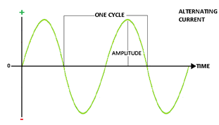
An alternating current (a.c.) is a current which continuously, changes in magnitude and periodically reverses in direction.`
i = I0 sin ωt = I0 sin (2π/T) t
Here I0 is the peak value of a.c.
(a) Current, I =I0 sin ωt
(b) Angular frequency, ω= 2πn (n is the frequency of a.c.)
(c) I =I0 sin 2πnt
-
Mean value of A.C or D.C. value of A.C.:-
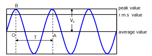
Mean value of a.c. is that value of steady current which sends the same amount of charge, through a circuit, in same time as is done by a.c. in one half-cycle.
(Iav)half cycle = (2/π)I0
Thus, mean value of alternating current is 2/π times (0.637 times) its peak value.
(Vav)half cycle = (2/π) V0
-
Average value of A.C. over a complete cycle:-
Iav = 0
The average value of a.c. taken over the complete cycle of a.c.is zero.
-
Root mean square value of a.c. or virtual value of a.c.:-
Root mean square value of alternating current is defined as that value of steady current which produces same heating effect, in a resistance, in a certain time as is produced by the alternating current in same resistance in same time. The r.m.s value of a.c.is also called its virtual value.
Irms = I0/√2
Root mean square value of alternating current is I/√2 times (or 0.707 times) the peak value of current.
Similarly, Vrms= V0/√2
Here V0 is the peak value of e.m.f.
-
Form Factor:-
Form Factor = rms value/average value = (V0/√2)/ (2 V0/π) = π/2√2
-
Current elements:-
(a) Inductive reactance:- XL = ωL
Here, ω = 2πn, n being frequency of a.c.
L is the coefficient of self-inductance of coil.
(b) Capacitative reactance:- Xc = 1/ωC
Here C is the capacity of the condenser
-
Capacitor in AC circuit:-
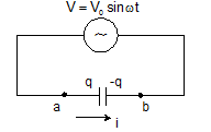 q = CV0sinωt
I = I0 sin(ωt +π/2)
V0 = I0/ωC
Xc = 1/ωC
-
Inductor in AC circuit:-
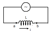 VL = L(dI/dt) = LI0ω cosωt
I = (V0/ ωL) sinωt
Here, I0 = V0/ ωL
XL = ωL
And the maximum current, I0 = V0/XL
-
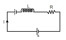
R-L circuit:-
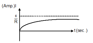
I = ε/R [1-e-Rt/L]
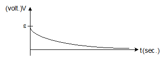
V = ε e-Rt/L
-
Graph between I (amp) and t (sec):-
-
Graph between potential difference across inductor and time:-
-
L-C Circuit:-
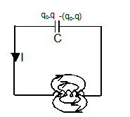
f = 1/2π√LC
q = q0 sin (ωt+ϕ)
I = q0ωsin (ωt+ϕ)
ω = 1/√LC
-
The total energy of the system remains conserved,
½ CV2 + ½ Li2 = constant = ½ CV02 = ½ Li02
-
Series in C-R circuit:-
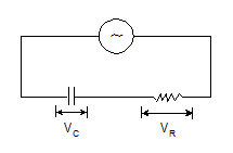
V = IZ
The modulus of impedance, |Z |= √R2+(1/ωC)2
The potential difference lags the current by an angle, ϕ = tan-1(1/ωCR)
-
Series in L-C-R Circuit:

V = IZ
The modulus of impedance, |Z |= √[R2+(ωL-1/ωC)2]
The potential difference lags the current by an angle, ϕ = tan-1[ωL -1/ωC)/R]
-
Circuit elements with A.C:-
|
Circuit elements |
Amplitude relation |
Circuit quantity |
Phase of V |
|
Resistor |
V0 = i0R |
R |
In phase with i |
|
Capacitor |
V0 = i0XC |
|
Lags i by 90° |
|
Inductor |
V0 = i0XL |
XL = wL |
Leads i by 90° |
-
Resonance:-
(a) Resonance frequency:- fr = 1/2π√LC
(b) At resonance, XL = XC, ϕ = 0, Z = R(minimum), cosϕ = 1, sinϕ = 0 nad current is maximum (=E0/R)
-
Half power frequencies:-
(a) Lower, f1 = fr – R/4πL or ω1 = ωr – R/2L
(b) Upper, f2 = fr + R/4πL or ω2 = ωr + R/2L
-
Band width:- Δf = R/2πL or Δf = R/L
-
Quality Factor:-
(a) Q = ωr/Δω = ωrL/R
(b) As ω = 1/√LC, So Q ∝ √L, Q ∝1/R and Q ∝ 1/√C
(c) Q = 1/ωrCR
(d) Q = XL/R or Q = XC/R
(e) Q = fr/Δf
-
At resonance, peak voltages are:-
(a) (VL)res = e0Q
(b) (VC)res = e0Q
(c) (VR)res = e0
-
Conductance, susceptance and admittance:-
(a) Conductance, G = 1/R
(b) Susceptance, S = 1/X
(c) SL = 1/XL and SC = 1/XC = ωC
(d) Admittance, Y = 1/Z
(e) Impedance add in series while add in parallel
-
Power in AC circuits:-
Circuit containing pure resistance:- Pav = (E0/√2)×(I0/√2) = Ev×Iv
Here Ev and Iv are the virtual values of e.m.f and the current respectively.
Circuit containing impedance (a combination of R,L and C):-
Pav = (E0/√2)×(I0/√2) cosϕ = (Ev×Iv) cosϕ
Here cosϕ is the power factor.
(a) Circuit containing pure resistance, Pav = EvIv
(b) Circuit containing pure inductance, Pav = 0
(c) Circuit containing pure capacitance, Pav = 0
(d) Circuit containing resistance and inductance,
Z = √R2+(ωL)
cosϕ = R/Z = R/[√{R2+(ωL)2}]
(e) Circuit containing resistance and capacitance:-
Z = √R2+(1/ωC)2
cosϕ = R/Z = R/[√{R2+(1/ωC)2}]
(f) Power factor, cosϕ = Real power/Virtual power = Pav/ErmsIrms
-
Transformer:-
(a) Cp = Np (dϕ/dt) and es = Ns (dϕ/dt)
(b) ep/es = Np/Ns
(c) As, epIp = esIs, Thus, Is/Ip = ep/es = Np/Ns
(d) Step down:- es < ep, Ns< Np and Is> Ip
(e) Step up:- es >ep, Ns>Np and Is< Ip
(f) Efficiency, η = es Is/ ep Ip
-
AC Generator:-
e = e0 sin (2πft)
Here, e0 = NBAω
View courses by askIITians


Design classes One-on-One in your own way with Top IITians/Medical Professionals
Click Here Know More

Complete Self Study Package designed by Industry Leading Experts
Click Here Know More

Live 1-1 coding classes to unleash the Creator in your Child
Click Here Know More

a Complete All-in-One Study package Fully Loaded inside a Tablet!
Click Here Know MoreAsk a Doubt
Get your questions answered by the expert for free